


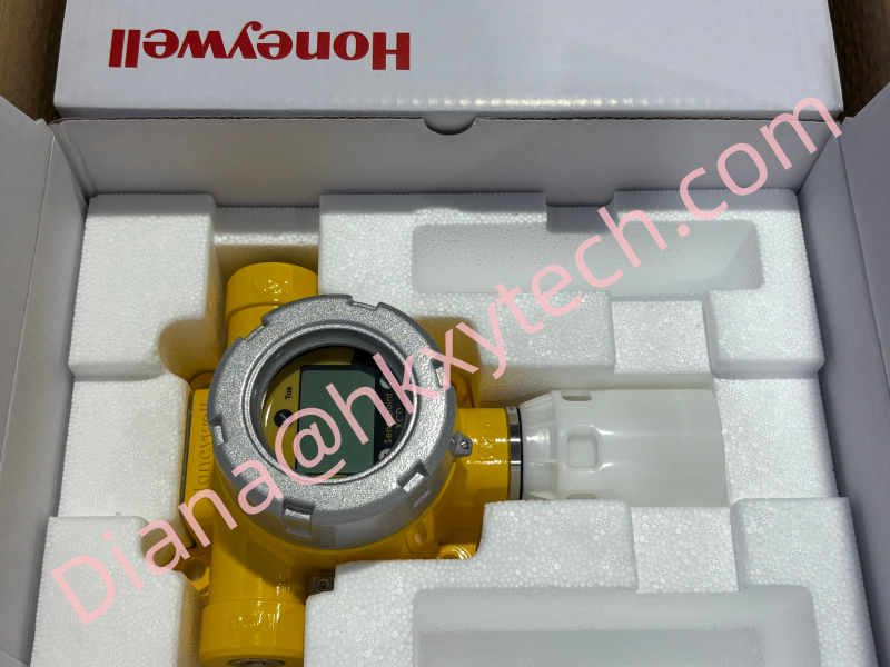
Safety-Focused Honeywell SPXCDALMTXO Sensepoint XCD Fixed Gas Detector Transmitter for Reliable Toxic, Oxygen and Flammable Gas Monitoring
Deploying the Honeywell SPXCDALMTXO Sensepoint XCD for Dependable Fixed Gas Monitoring: Siting, Integration, Commissioning and Maintenance Guidance
The Honeywell SPXCDALMTXO is associated with the Sensepoint XCD fixed gas detection platform, designed to provide local indication and plant-system connectivity for industrial gas monitoring applications.
A successful Honeywell SPXCDALMTXO installation depends on more than mounting the transmitter. Gas risk, sensor location, airflow, electrical interfaces, alarm philosophy, calibration access and proof-testing requirements must be engineered as one complete detection function.
Start with the Hazard Scenario
Before selecting a location for the Honeywell SPXCDALMTXO, identify the target gas, credible leak sources, release pressure, ventilation pattern and occupied areas. Gas density influences whether the sensing point should be positioned high, low or near a potential release path.
Environmental conditions also matter. Temperature, humidity, washdown, dust, vibration and chemical exposure should be compared with the approved configuration and sensor limits. The Honeywell SPXCDALMTXO must remain accessible for inspection, calibration and sensor replacement without placing technicians in unnecessary danger.
Siting Questions for the Engineering Review
-
Where can the target gas realistically escape?
-
How will ventilation or outdoor wind move the gas?
-
Could equipment, walls or pipework shield the Honeywell SPXCDALMTXO from the release?
-
Can calibration gas be applied safely at the installed position?
-
Will operators be able to see the local status display?
-
Does the installation require a remote sensing arrangement?
Honeywell states that compatible toxic and oxygen sensors can be mounted remotely up to 30 m from the transmitter in applicable Sensepoint XCD arrangements. The exact sensor and accessory compatibility must be verified for the Honeywell SPXCDALMTXO configuration.
Connect the Detector to the Plant Safely
The Sensepoint XCD platform supports an industry-standard 4-20 mA signal, selectable sink or source operation, relay outputs and Modbus communications in supported configurations. The Honeywell SPXCDALMTXO loop drawing should clearly define power supply, signal type, grounding, cable shielding, relay use and receiving-system scaling.
Official platform information lists a nominal 24 VDC supply, with published operating ranges depending on the configuration. Confirm the exact Honeywell SPXCDALMTXO voltage requirement and available current at the end of the cable, including voltage drop and startup demand.
Interface Checklist
-
Power: verify polarity, supply range, protective device and cable voltage drop.
-
Analog signal: confirm 4-20 mA sink or source topology and controller scaling.
-
Relays: define alarm and fault relay action, contact rating and fail-safe behavior.
-
Digital communication: document RS485 polarity, Modbus address, baud rate and termination where used.
-
Grounding: follow the approved earthing and shield arrangement.
-
Cable entries: use certified glands, seals and stopping plugs appropriate to the installation.
The Honeywell SPXCDALMTXO should not be energized until hazardous-area requirements, cable entries and enclosure integrity have been inspected by qualified personnel.
Commissioning Route
Step 1 - Identity check
Compare the Honeywell SPXCDALMTXO nameplate, sensor type, gas, range, approvals and enclosure material with the purchase specification.
Step 2 - Power-up observation
Allow the required stabilization period and check the local display for normal status or diagnostic messages.
Step 3 - Configuration review
Verify measuring range, alarm thresholds, latching behavior, relay assignments, analog-output mode and communications settings.
Step 4 - Gas response test
Apply the correct certified test gas using the specified flow and method. Confirm that the Honeywell SPXCDALMTXO responds, reaches the expected value and returns correctly after gas removal.
Step 5 - End-to-end proof
Confirm that local indication, 4-20 mA signal, alarms, relays, Modbus data and control-room annunciation all agree.
Use the Local Status Without Opening the Enclosure
The Sensepoint XCD platform provides a tri-color backlit display and magnetic-switch operation. This allows supported Honeywell SPXCDALMTXO functions to be reviewed or configured without routinely opening the transmitter enclosure.
-
Green indicates normal operating status on the platform.
-
Yellow is used for fault indication.
-
Red is used for alarm indication.
-
Maintenance inhibit helps prevent unwanted process actions during authorized service.
Site procedures must control who may change Honeywell SPXCDALMTXO settings, how maintenance inhibit is communicated and how the detector is returned to service.
Maintenance Should Follow Risk, Not Habit
Inspection and calibration intervals should reflect the target gas, sensor technology, environmental exposure, regulatory requirements and site experience. A clean-looking Honeywell SPXCDALMTXO is not proof that the complete detection loop will respond correctly.
Routine work should examine enclosure condition, cable entries, display status, sensor contamination and mounting security. Perform a functional gas test and verify the signal at the receiving system. Record as-found and as-left values so gradual drift can be identified.
Replacement and Spare Planning
Store the complete Honeywell SPXCDALMTXO ordering code, sensor gas and range, firmware information where applicable, alarm setpoints, calibration records and Modbus settings with the asset file.
When replacing a sensor or transmitter, verify compatibility rather than assuming all Sensepoint XCD components are interchangeable. After service, repeat the end-to-end test and remove maintenance inhibit only after the Honeywell SPXCDALMTXO and receiving system have returned to normal.
The Honeywell SPXCDALMTXO can support clear local status, flexible plant integration and maintainable fixed gas monitoring when it is applied within a documented safety strategy. Confirm the complete Honeywell SPXCDALMTXO code, target gas, approvals and interface requirements before ordering, and preserve commissioning evidence throughout the detector lifecycle.
